Vibration Isolator Induced Resonance

-
Vibration isolators are mechanical elements that prevent/limit the vibrations occurring in the machine from passing to the ground and the vibrations of the ground from passing to the machine.
-
These elements, which generally contain viscoelastic materials, fulfill their vibration isolation function as a result of their mechanical properties, "Stiffness (K-spring coefficient)", "Mass (M)" and "Damping (D)" ratios. There are also versions with spring and damping elements mounted separately.
Case Study:
-
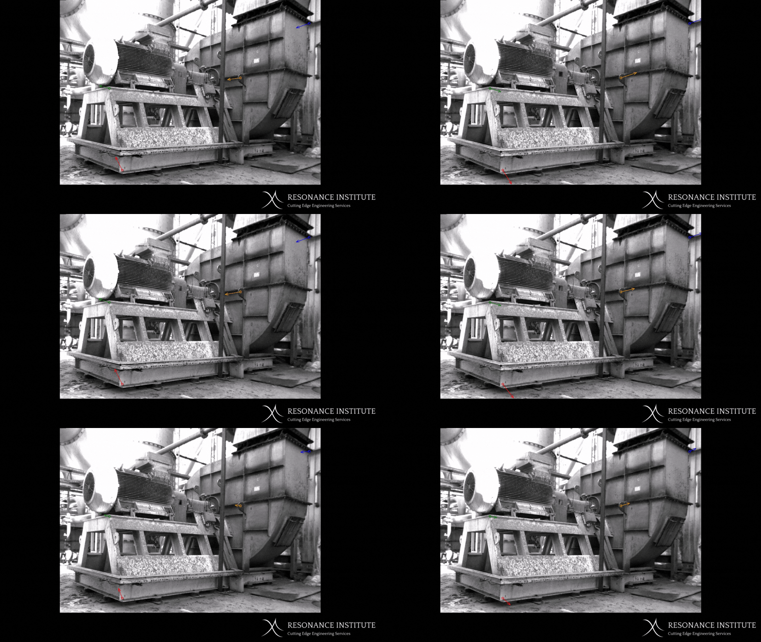
In the "Motion Amplification" measurements made on a fan with a structural vibration problem, "Rigid body modes" resulting from the application of an isolator could be observed.
-
Rigid body modes are natural frequencies (created knowingly and intentionally) as a result of the stiffness of the insulator and the mass of the machine on it.
-
The vibration isolation starts working from 1,414 times these natural frequencies, which occur as a result of the isolator mechanical properties. Therefore, starting from 1,414 times the highest of these natural frequencies, vibration problems such as unbalance, misalignment, etc. occurring in the machine do not pass to the ground, or are not transmitted from the ground to the machine (or are transmitted to a certain extent).


Rigid Body Modes:

-
In order to detect the structural vibration problem experienced in this equipment, a runup test was first performed and the spectrum waterall graph seen on the left was obtained.
-
As can be seen, vibration increases occur in three different frequency regions. When these frequencies were examined separately, it was understood that these were rigid body modes resulting from the application of isolators.
-
The natural frequency appearing at 16Hz is an elastic structural natural frequency and is not included in this case analysis.
Rigid Body Modes:
-
The X, Y and Z coordinate directions and coordinate system are superimposed on the photo on the right.
-
The natural frequencies at 8Hz, 11Hz and 24Hz detected in this fan example are listed as follows, along with their mode shapes (vibration shapes).

8Hz - Y-axis Translational Mode:

-
In the motion amplification video seen above, the translational mode in the Y direction is clearly visible. This mode occurs at 8Hz and vibrates the fan as seen above during the equipment runup. This mode is quite far (except for 20%) of the fan's nominal rotation speed of 1480RPM (24.8Hz), so it does not pose a threat.
11Hz - Z axis Rotational Mode:

-
In this motion amplification video, the rotational mode around the Z axis is seen. This mode occurs at 11Hz and causes the fan to vibrate as seen above during the equipment runup. This mode is quite far (except for 20%) of the fan's nominal rotation speed of 1480RPM (24.8Hz), so it does not pose a threat as well.
24Hz - Y axis Rotation Mode:

-
This motion amplification video shows the rotational mode around the Y axis. This mode occurs at 24Hz and causes the fan to vibrate as seen above during the equipment runup. This mode is very close (within 20%) to the fan's nominal rotation speed of 1480RPM (24.8Hz), so high vibration problems occur in cases of unbalance in the equipment. Vibration can be reduced by on-site balancing work, but if unbalance occurs again, high vibration values will still be observed.
-
The reason why this mode occurs at 24Hz is because the isolators hardness (and therefore their stiffness) and/or the number of isolators are not correct. In some cases, this situation occurs at the design stage (wrong design/isolator selection), and most of the time, the isolators lose their properties and harden over time.
-
For this reason, the selection of isolators should be made through engineering calculations, and the mechanical properties of the isolators should be checked periodically.
